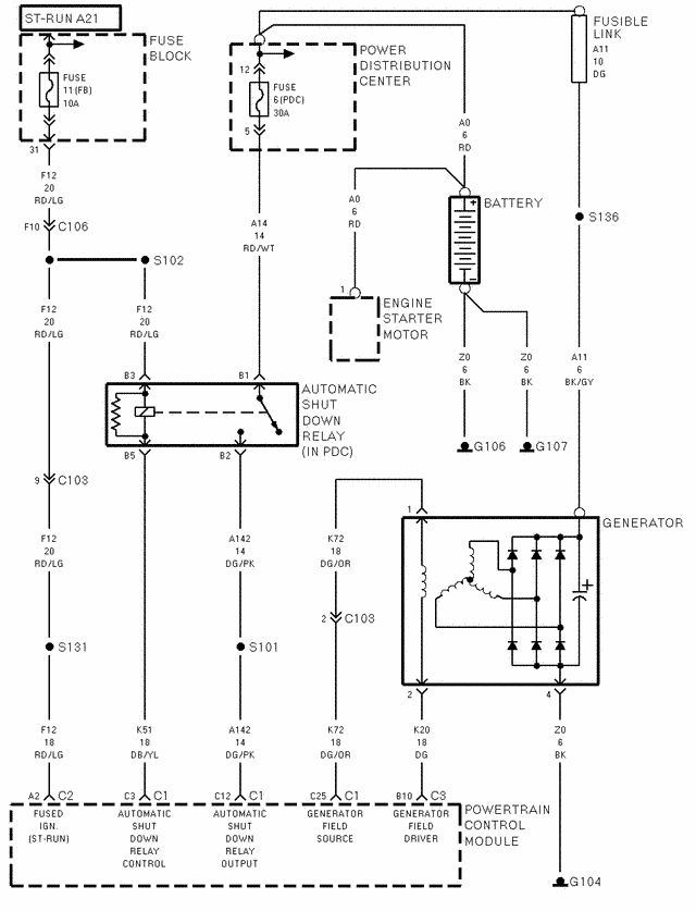
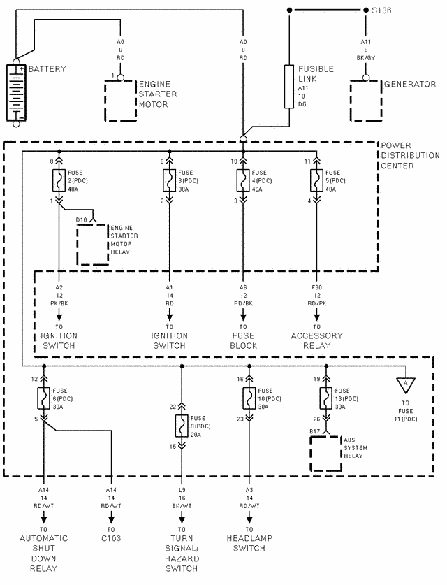
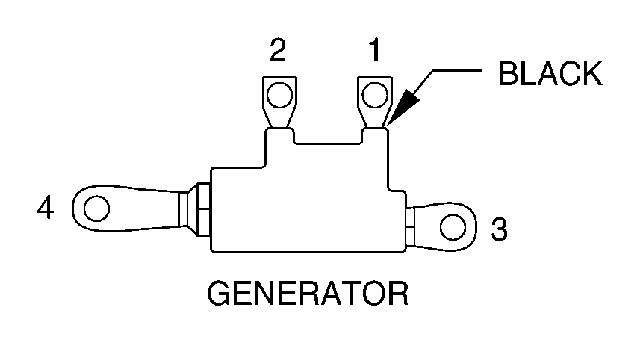
CAVCIRCUITFUNCTION1K72 18DG/ORGENERATOR FIELD SOURCE (+)2K20 18DGGENERATOR FIELD DRIVER3--4Z0 6BKGROUND
CHARGING SYSTEM OPERATION
The charging system consists of:
- Generator
- Electronic Voltage Regulator (EVR) circuitry within the Powertrain Control Module (PCM)
- Ignition switch (refer to Ignition System for information)
- Battery (refer to Battery for information)
- Battery temperature sensor
- Generator Lamp (if equipped)
- Check Gauges Lamp (if equipped)
- Voltmeter (refer to Instrument Panel and Gauges for information)
- Wiring harness and connections (refer to Wiring for information)
The charging system is turned on and off with the ignition switch. When the ignition switch is turned to the ON position, battery voltage from the powertrain control module (PCM) is supplied to the generator rotor to produce a magnetic field. This is done through one of the two field terminals at the rear of generator.
The amount of DC current produced by the generator is controlled by the EVR (field control) circuitry contained within the PCM. This circuitry is connected in series with the second rotor field terminal and ground.
A battery temperature sensor, located in the battery tray housing, is used to sense battery temperature. This temperature data, along with data from monitored line voltage, is used by the PCM to vary the battery charging rate. This is done by cycling the ground path to control the strength of the rotor magnetic field. The PCM then compensates and regulates generator current output accordingly.
All vehicles are equipped with On-Board Diagnostics (OBD) All OBD-sensed systems, including EVR (field control) circuitry, are monitored by the PCM. Each monitored circuit is assigned a Diagnostic Trouble Code (DTC) The PCM will store a DTC in electronic memory for certain failures it detects. Refer to On-Board Diagnostics in Group 25, Emission Control System for more DTC information.
The Check Gauges Lamp (if equipped) monitors:
charging system voltage, engine coolant temperature and engine oil pressure. If an extreme condition is indicated, the lamp will be illuminated. This is done as reminder to check the three gauges. The signal to activate the lamp is sent via the CCD bus circuits. The lamp is located on the instrument panel. Refer to Instrument Panel and Gauges for additional information.
CHARGING SYSTEM RESISTANCE TESTS
These tests will show the amount of voltage drop across the generator output wire, from the generator output (B+) terminal to the battery positive post. They will also show the amount of voltage drop from the ground (-) terminal on the generator to the battery negative post. Typical generator wiring harnesses are shown in
Generator Terminals (Typical Wiring Harness Shown) or
Generator Terminals (Typical Wiring Harness Shown) Wiring harness routing as shown may be slightly different depending on vehicle model and/or engine. Refer to Wiring Diagrams for additional information.
A voltmeter with a 0 - 18 volt DC scale should be used for these tests. By repositioning the voltmeter test leads, the point of high resistance (voltage drop) can easily be found.
PREPARATION
- Before starting test, make sure battery is in good condition and is fully-charged. See Battery for more information.
- Check condition of battery cables at battery. Clean if necessary.
- Start the engine and allow it to reach normal operating temperature.
- Shut engine off.
- Connect an engine tachometer.
- Fully engage the parking brake.
TEST
- Start engine.
- Place heater blower in high position.
- Turn on headlamps and place in high-beam position.
- Turn vehicle interior lamps on.
- Bring engine speed up to 2400 rpm and hold.
- Testing (+) circuitry:
- Touch the negative lead of voltmeter directly to battery positive post.
- Touch the positive lead of voltmeter to the B+ output terminal stud on the generator (not the terminal mounting nut) Voltage should be no higher than 0.6 volts. If voltage is higher than 0.6 volts, touch test lead to terminal mounting stud nut and then to the wiring connector. If voltage is now below 0.6 volts, look for dirty, loose or poor connection at this point. Also check condition of the generator output wire-to-battery bullet connector (if equipped) Refer to iring for connector location. A voltage drop test may be performed at each (+) connection in this circuit to locate the excessive resistance.
- Testing (-) circuitry:
- Touch the negative lead of voltmeter directly to battery negative post.
- Touch the positive lead of voltmeter to the ground terminal stud on the generator case (not the terminal mounting nut) Voltage should be no higher than 0.3 volts. If voltage is higher than 0.3 volts, touch test lead to terminal mounting stud nut and then to the wiring connector. If voltage is now below 0.3 volts, look for dirty, loose or poor connection at this point. A voltage drop test may be performed at each (-) connection in this circuit to locate the excessive resistance. This test can also be performed between the generator case and the engine. If test voltage is higher than 0.3 volts, check for corrosion at generator mounting points or loose generator mounting.


