You are using an out of date browser. It may not display this or other websites correctly.
You should upgrade or use an alternative browser.
You should upgrade or use an alternative browser.
Nutter Bypass and Vacuum Lines
- Thread starter dekr
- Start date
Saddle Tramp
New member
Wow. Here I am googling images of post-nutter vacuum lines, and what do I come upon but my own damned post!
Thank you for the images, Saddle Tramp, and my deepest apologies for not thanking you months ago. I believe that was around the time I decided to give up on repairs and run it into the ground... 8 months later, it hasn't happened yet, so it looks like I'm going to rebuild the money pit after all.
From the top diagram (I don't have a Weber), it looks like the decel valve and the air filter housing EGR lines aren't necessary at all. True?! You mean, I can get rid of those damned lines practically lying on top of my engine?!
Saddle Tramp
New member
You eliminate a lot of troublesome plumbing with the Nutter Bypass, that is largely the point. However depending upon your local smog requirements you will no longer pass a visual inspection.
As far as the EGR valve goes, I would not be too hasty to remove it. The EGR even though it is a smog feature plays a very important role; it functions to lower the temperature inside the cylinder during combustion. At first blush you would think the higher the temp the better the combustion the better the deal. Well in reality the higher temps without the EGR produce more smog and are also not so good for your engine. The EGR tames both issues while virtually cost you nothing to run as far as performance and probably extends the life of your motor. I always leave them hooked up.
As far as the EGR valve goes, I would not be too hasty to remove it. The EGR even though it is a smog feature plays a very important role; it functions to lower the temperature inside the cylinder during combustion. At first blush you would think the higher the temp the better the combustion the better the deal. Well in reality the higher temps without the EGR produce more smog and are also not so good for your engine. The EGR tames both issues while virtually cost you nothing to run as far as performance and probably extends the life of your motor. I always leave them hooked up.
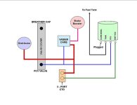
That diagram shown on top is in error and should not be used or provided to anyone on a technical forum.
Notice how it is indicating that the "S" ported vacuum tube being shared with the distributer vacuum advance and then supplying both sides of the CTO.
While one side is feeding the cannister purge valve which is designed without having a bleed and if deterioration hasn't taken a toll with that valve then all is fine with that.
The other side of the Dual CTO feeds the EGR, it is a bleeding device and will diminish the amount of vacuum to the distributer equal to the amount of bleed, so that much less vacuum timing advance will occur.
Another point to make is that the fifth or unused Dual CTO nipple will have a bleeding to atmosphere cap installed. It should be removed and the nipple plugged.
Which ever carb you use will most likely have an "E" ported nipple and it is the one which should be routed to the side of that Dual CTO which is feeding the EGR if you are using "S" ported vacuum advance.
Last edited by a moderator:
Sorry, I was lumping things together that aren't necessarily related. I meant the just the lines under and around the air filter housing. But thanks for the info, I didn't know that about the EGR. I'll give it all a shot today.
mcmud, the Nutter Bypass tells you to change the dizzy vacuum from manifold to ported. Are you saying that instead of making a T with the existing line running from the CTO to the "S", I should move the existing CTO line over to "E", and dedicate the "S" entirely to my distributer?
I haven't seen mention of this anywhere else while researching the bypass. Do you have a source? I'm just a bit skeptical because the image above confirmed everything I came up with by modifying sprynet's image to omit the computer controlled areas, and then removed a few more things (which is the whole point of this game).
Saddle Tramp
New member
That diagram shown on top is in error and should not be used or provided to anyone on a technical forum.
Notice how it is indicating that the "S" ported vacuum tube being shared with the distributer vacuum advance and then supplying both sides of the CTO.
While one side is feeding the cannister purge valve which is designed without having a bleed and if deterioration hasn't taken a toll with that valve then all is fine with that.
The other side of the Dual CTO feeds the EGR, it is a bleeding device and will diminish the amount of vacuum to the distributer equal to the amount of bleed, so that much less vacuum timing advance will occur.
Another point to make is that the fifth or unused Dual CTO nipple will have a bleeding to atmosphere cap installed. It should be removed and the nipple plugged.
Which ever carb you use will most likely have an "E" ported nipple and it is the one which should be routed to the side of that Dual CTO which is feeding the EGR if you are using "S" ported vacuum advance.
I've had these diagrams kicking around my computer for so long I couldn't even tell you where I got them from but thanks for the heads up, I will delete the incorrect one so I don't confuse anyone else.
Last edited by a moderator:
Sorry, I was lumping things together that aren't necessarily related. I meant the just the lines under and around the air filter housing. But thanks for the info, I didn't know that about the EGR. I'll give it all a shot today.
Then I have misunderstood.
A point to make about omitting those "lines under and around the air filter housing".
If you omit the TAC system hoses then you will no longer have the warm air feed to the carb during the cold run and you will be forced to by some means jamb the cold air door open. Otherwise it will not receive adequate air supply, run rich and cause a host of issues with that.
Then the other you maybe contemplating removing is the EGR TVS that may be a mistake depending on the area you live. It prohibits the signal which has passed through the CTO from reaching the EGR during cold ambient temperatures.
Pretty much. If you chose to use the ported vacuum source for timing advance then you would not have the full benefit of advance while that source is shared with any bleeding device.mcmud, the Nutter Bypass tells you to change the dizzy vacuum from manifold to ported. Are you saying that instead of making a T with the existing line running from the CTO to the "S", I should move the existing CTO line over to "E", and dedicate the "S" entirely to my distributer?
The Dual CTO is just that. One side is independent of the other. As I mentioned that one side is shown supplying signal to the cannister purge signal valve. If that valve is not leaking all is well there.
That other side which is shown feeding the EGR should be feed a signal from the "E" vacuum source. That is its purpose.
As far as the vented to atmosphere cap now that the ignition is nuttered the air intake at that cap is the same as an air leak, some folks will refer to it as a vacuum leak.
I haven't seen mention of this anywhere else while researching the bypass. Do you have a source? I'm just a bit skeptical because the image above confirmed everything I came up with by modifying sprynet's image to omit the computer controlled areas, and then removed a few more things (which is the whole point of this game).
The top diagram is an error. If you have modified any system and came up with that layout your vacuum system is in error.
Give it a go for yourself and try to have either of those devices hold a vacuum. A hand held vacuum pump will normally create 18"Hg with a single stroke, if you do not have one insert a tube running from the EGR into your mouth and have a go with that.
The source is myself and in this case via use of this forum. An avenue of enlightenment might be yourself.
Spread the word once any skepticism is put to rest.
Saddle Tramp
New member
Have these diagrams been fixed or do they still contain errors as mcmud pointed out. If they are still incorrect does any one have the correct ones. Looking for diagram that works with Carter BBD.
No, the top one has not been corrected. I would delete it if I cound but I don't seem to be able too.
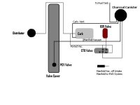
Maybe this one will do.
It indicates the use of the "E" ported nipple for the EGR...via the CTO and then the Thermal Vacuum Switch.
Then it is showing the use of the "S" ported nipple controlling the (non-bleed)canister purge signal...and manifold vacuum as the cold run source for spark advance, then after the warm-up the CTO switches over to the "S" ported source.
Depending on the build year, your distributer was set up to use either manifold or the "S" or the variation of the two as is shown in this diagram. Some adjustment may be necesary.
Welcome to Jeepz...if you will, be sure to include a general description of the vehicle, its equipment as well as the devices you hope to control.
Attachments
BDurrant
New member
McMud:
I just completed the 'Nutter" and ran my vac according to the schemmmatic in question. it's warm here and I don't know if i will have problems when it cools down. I researched the nutter for quite some time before I did it and found tons of schm that completely support the diagram you question. as for an example go to "adventures under the hood" . this is a great site. well presented and the vac system completely explained. the diagram is there for the STOCK vac setup and it shows the same things that you say are wrong. I have all the hoses from my stock setup and I have nothing but time so I will route the system as shown in the "supposed correct diagram" and see how that works. I have some questions concerning that diagram though. just labeling questions. so when you answer this "I think you will" I'll ask them. The main point here is to get our rides running as good as possible. If your right and all the other info is wrong, then tons of Jeepers need to know!
I just completed the 'Nutter" and ran my vac according to the schemmmatic in question. it's warm here and I don't know if i will have problems when it cools down. I researched the nutter for quite some time before I did it and found tons of schm that completely support the diagram you question. as for an example go to "adventures under the hood" . this is a great site. well presented and the vac system completely explained. the diagram is there for the STOCK vac setup and it shows the same things that you say are wrong. I have all the hoses from my stock setup and I have nothing but time so I will route the system as shown in the "supposed correct diagram" and see how that works. I have some questions concerning that diagram though. just labeling questions. so when you answer this "I think you will" I'll ask them. The main point here is to get our rides running as good as possible. If your right and all the other info is wrong, then tons of Jeepers need to know!
Similar threads
- Replies
- 6
- Views
- 15K
- Replies
- 3
- Views
- 851