Contour Fan Controller~Mine finally gave out after 15 years

Turbogus

New member
Hi gang, I've been tooling along with the Contour~actually Mystique dual fan setup for over a decade now on 'Black Betty.' Fortunately I was in town when this failure occurred.

https://uniim1.shutterfly.com/ng/se...ia/1684659539116380/medium/1606616581/enhance

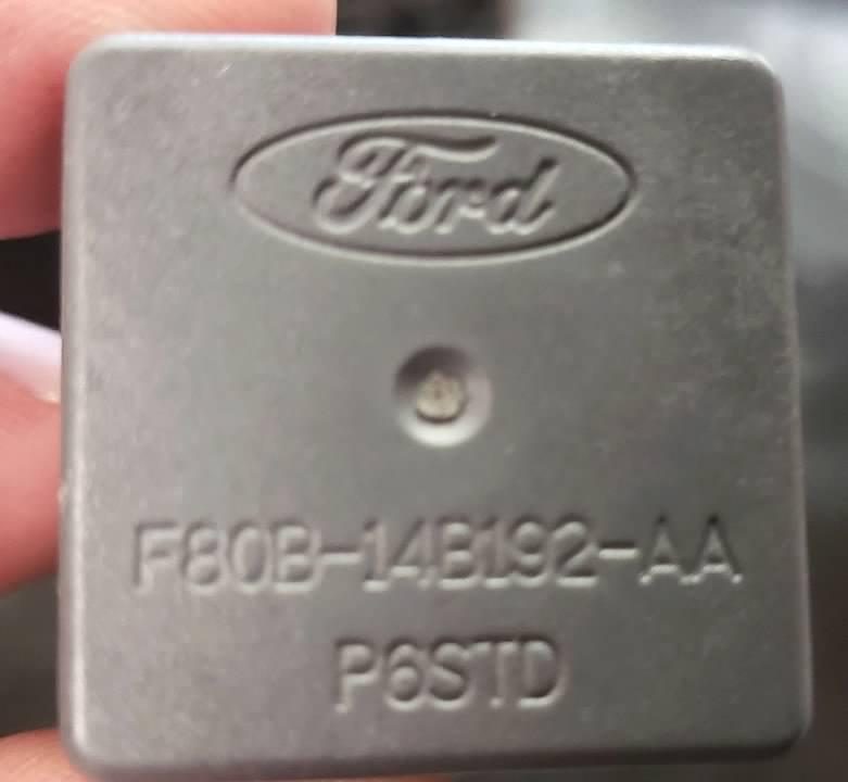
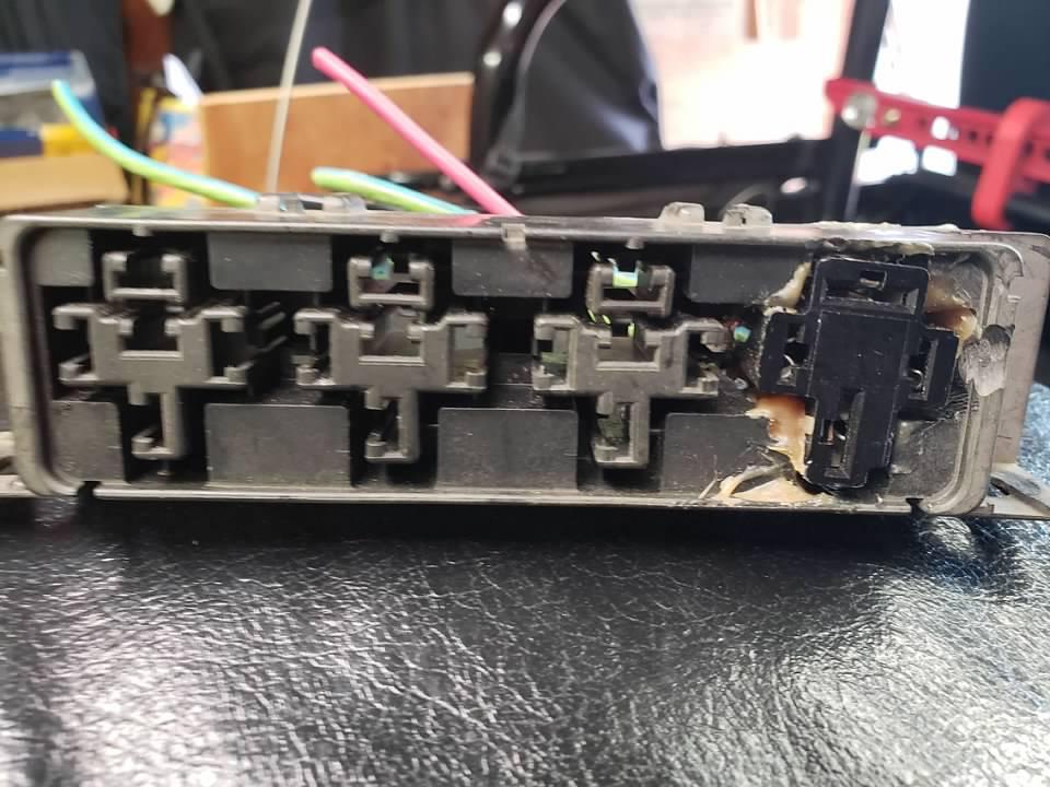
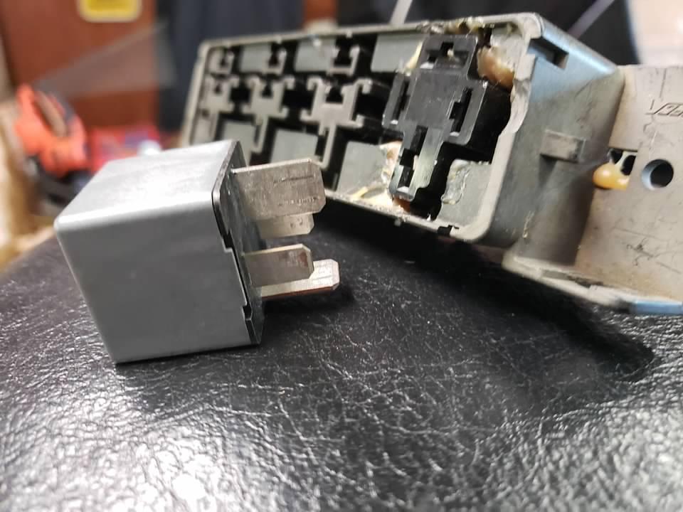
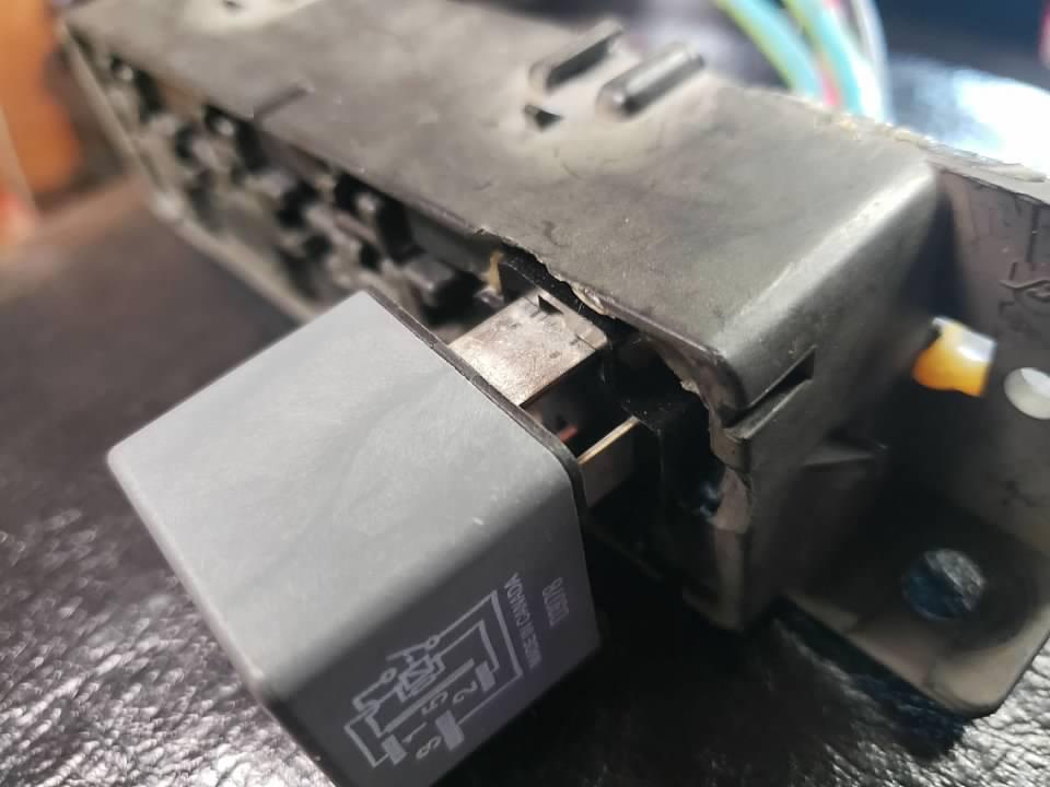
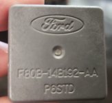
From the wiring (shown in the link) all of my wiring is OK. That Hayden controller at the top however is another matter. As near as I can figure with my multimeter the PCM failed. No surprise as the relays are rated at 40 amps and it appears too many times overheated. I wired each speed with its own controller. I thought that the multiple stepped relays would've tempered this (and it has) more permanently. Are there modern controllers with threaded NPT senders and capable of override (On-Off-High Speed On) that can candle the upwards of 70 amp spikes?

Thanks and a lift of the lynch lid for your responses.

Gus
 
Last edited:
Hi JPN, When I was doing all of my contact checking things looked good and hotwiring the fans they both work on Hi and Low. I think its the Hayden 3651 controllers went bad x2. 89-036-038-01.jpg

https://uniim1.shutterfly.com/ng/se...7/media/25053956774/medium/1606617042/enhance


One for each speed. I like these on account of their adjustability and the NPT threaded sender. What I mean is the plastic components of the Circuit Board are cheesy, namely the plastic adjustment screw. I've protected them by encasing them in a small plastic box, but I think it may be the Amp spike over the years and underhood temperatures is what made them ultimately fail. Is there anything like these that are more robust?
 
Last edited:
Contact checking is one thing. Current checking is another. If your fan has a flyback diode and it goes south you will have an issue. A little rust dragging on the shaft or bad bearing…increased running current and heat. Same happens to the HVAC fan and wires and connectors melt.

Id have to do some digging on the controller to find a 80 or 100 amp controller.


Never look down on anyone unless you are helping them up - Jesse Jackson
 
Last edited:

I think I found one by Hayden again, it's for one fan but rated at 65 amps IF I remember correctly. I seem to recall when I first changed out the PO's pusher fan arrangement that Fords 70 amp relays were placed to contain those spikes. The blade width is considerably wider than standard Bosch relays.

enhance.jpg

enhance (2).jpg

enhance (5).jpg

enhance (3).jpg
 
Last edited:
Today I'm checking the relay contacts on the Chinese senders to make sure of the power from the switch and ground. I'm also going to try jumping it to see if the problem really lies on the circuit board.
 
I was able to check the grounds~correct and signal~correct I then jumped power from the control board relay socket to battery I heard the secondary relay click and the fans started working. I did the same on the high speed control board and it worked as well. I think the problem is still on the circuit board and possibly related to the potentiometers.
 

I was looking at the Flex a lite fan controller on Summit and it has the NPT sender that I use and a more robust potentiometer than the Haydens I'm using but the description says Single/Dual fans but the installation .pdf only mentions one fan I wonder if I can split the output to fans on that setup safely.
 
I use a flex-a-lite black magic 485 with their controller. The fans running current is 18A and came with a 20A fuse that kept blowing. The starting current was 30+ A so I used 40A fuses and thicker gauge wire.

Eventually (10yrs) the motor failed. On its way out, it blew fuses and melted wires. They sell replacement parts so the motor was replaced and all is fine.

Anyhow I’d check the current rating of the controller vs the fans running plus starting current.

You might call them to scope out which controller. They were helpful when the motor failed.

Looking at different vendors controllers a few specify cannot be used with Taurus and other fans.

In another thread elsewhere people using a volvo switches and controller on their taurus fan

Never look down on anyone unless you are helping them up - Jesse Jackson
 
Last edited:

I fired up the Jeep today and mowed the lawn~dandelions and let the Jeep idle up to operating temperature. I then adjusted the potentiometer screw for low speed and it began working. I could not get the high speed to work but did verify that the low speed shut off after the motor cooled down post heat soak.
I found my original pieces to this fan project and I have no fewer than three Ford F80B-14B192-AA 70 Amp relays.


enhance-1.jpg


I also found the dingus I grafted in the Socket into a Ford relay pack

enhance-2.jpg


And all I have to do is wire in the signal and ground wiring from a new Hayden 3651

enhance-3.jpg


enhance-4.jpg
 

Attachments

  • 20210610_170317 (2).jpg
    20210610_170317 (2).jpg
    772.5 KB · Views: 32
I understand that as I didn't include photos of the wiring some may suspect that it's a hack job. I just wanted to point out that ALL the wired connections are soldered, and whenever possible I use 3M heat shrink tubing, if not Pico or some other heat shrink. Also all of these circuits are loomed. So there's no weak links (solderless connectors, electrical tape, etc)
That being said I un-loomed the wiring and checked for voltage on the Pos + supply wire to the high speed relay and found battery voltage, also the hot for the high speed override functions at battery voltage when I flip the dash switch. Checking my wiring for continuity or overheating, short circuits showed no issues. So I'm back to the circuit board on the controller. The new one is arriving tomorrow, but I'll have little time this week to work on it.
 
I got the new controller and not only is the new style equipped with two fuses that the old one didn't have, the threaded sender connections seem more robust. :D
I may get into this tomorrow, it's Jeep season after all.
 

Edit: It came to me while I was just falling asleep the other day. Check the ground from the Circuit Board of the controller to my ground bus bar. Result: Failure apparently on the board there is a broken ground connection. So no longer a mystery.
 
I thought that perhaps I needed to move the box that contained the pair of controllers (one of which had failed) further away from the Radiator and perhaps it was radiant heat that caused the failure. However, when I idled the motor to operation temp and using the remote thermometer on varied parts of the Engine Compartment it was already in the coolest spot at 86# So I guess it was a matter of age and vibration that did the controller in after 15 years. The controller for the Low speed fan is hanging in there although I boogered up the plastic adjustment screw.
 
Post a pic of the fail location


Never look down on anyone unless you are helping them up - Jesse Jackson
 

I got the 70amp relay plug wiring done by the graft I had shown in a previous photo, now onto the controller package. One I get the old controller out I'll disassemble it and see if I can expose the board for a photo.
 
:verry-happy: Got the new controller spliced in and everything is working now. I haven't hacked the old one out of the circuit yet (I spliced in with solder and 3M heat shrink) So next go I'll remove the old controller and it's wiring and open it up. I'd lay even money some solder came loose. Going to insert some foam rubber into the container I keep the controllers in to cushion them.
 
[FONT=&quot]Man, I couldn't believe what a task it would be to find some scrap foam rubber, ultimately I had to hack up some children's toys but I got it all cut to fit and I'm just waiting for the weather to cool down a bit so I can remount the controller case to the inner fender and re~loom all of the wiring that I disassembled when I initially was chasing this gremlin. May have at it again next wednesday.[/FONT]
 

I took BB out for a test drive today and the temperature was steady at 190* :verry-happy:
 
Back
Top