Wiring harness questions

mrhc

New member
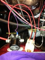
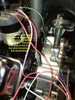
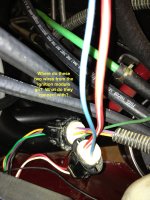
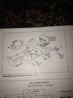
I am trying to install a Painless wiring harness in my 79 CJ-7. It has a 304 V8 and I do not understand the connections from the electronic ignition to the coil to the solenoid. The diagram in the instructions mentions wires that are not present in the harness. I am not sure what the resistor wire looks like so I'm not sure I have one. I took a lot of connections and wires off the old harness because the connectors for the ignition were not in the new one. I have included some pics of things and asked some more questions. Also, there is not a connection in the harness for the brake proportioning valve or for the transmission wire. How would I go about getting them connected? They may have connections already built in, I just don't know a lot about wiring so I don't know where they go. I included the pic from the instructions that I used. As far as I can tell I have a Motorcraft Electronic Ignition System. At least mine looks the most like that picture in the instructions. Ha. Thanks for the help, this is what is keeping me from trying to crank it.
 

Attachments

  • solenoid connections.jpg
    solenoid connections.jpg
    2.1 MB · Views: 33
  • positive coil.jpg
    positive coil.jpg
    1.9 MB · Views: 31
  • Ignition.jpg
    Ignition.jpg
    1.7 MB · Views: 23
  • IMG_0416.jpg
    IMG_0416.jpg
    2.1 MB · Views: 33

I regret I cannot do a righteous job of mapping out the connections at the moment , but I have a wiring diagram of a 1980 CJ and will try to help out . I need time and hope to do it soon . So far , the pic of the ignition resister is wired wrong. The side terminals of the starter solenoid (large) are for the battery cables from positive side of battery only , battery positive to one large post and cable to starter from other large post.there must be a power wire from large post on battery positive side of starter solenoid to ignition switch power terminal to supply power for all power circuits for fuse box as well . Negative battery cable to engine block , S terminal to starter terminal on ignition switch via the clutch start switch or neutral safety switch if automatic but through ignition module to S terminal on starter solenoid , must research that first. I terminal to ignition terminal on ignition switch also through ignition module , must research as well . The ignition resister is wired between ignition coil positive and starter solenoid I terminal but have to see how ignition module is wired with this . The pic of the two wires from ign. module ; lt. Blue to neutral safety or clutch start switch to solenoid terminal on ignition switch , this will crank starter. The red wire will go to ignition switch ignition terminal through I terminal on starter solenoid to ignition coil positive. I cannot correctly address color codes from painless wiring on horseshoe clip to ign. Coil since there is a red /black wire(s) and diagram shows red/white wire. This is all rough , will have to look closer to get correct routing of each wire. Basically , S terminal on ignition switch will go (roundabout) to S terminal on starter solenoid and I terminal on ignition switch will go (roundabout) to I terminal on starter solenoid to crank starter. Again , I need to take best look at diagram and repost. Will do so as soon as I can . Now that i have totally confused you , i must help to get this right for you to understand whatve posted thus far. Thank you for your post . Greg
 
Last edited:
image-1279658262.jpg


image-3559371240.jpg


image-27270313.jpg

These pictures may help , at least they include the ford dura spark ignition module to clarify connections . Hope this helps until I can study and map out connection by connection.
 
Im a bit confused!!! Your diagram shows a electronic ignition with control module, it also shows a ballist resister???? As far as I know, ballists are used with points ignitions, not electronic. The diagrams greg posted don't show a ballist, you also mentioned a resistor wire and again a resistor wire was on old points ignitions that used ballist. Are you sure you are using the right diagram for 79?? Ive had a couple 79,s and they did not have ballist resistors or resistor wires. I switched one of them to points ignition and had to install those items. A resistor wire will have a cloth or canvas looking covering. The ballist is really throwing me off here, I don't know why they are showing that in the same pic as the other components for a electronic ignition. I would call painless and ask, or someone please educate me on this. The ballist is used to drop volts from the ignition to the points, because the points cant receive a full 12v all the time and the ballist drops those volts down to around 9v so your points don't burn up..
 

69jeepcj, I'm just using the diagram in the instructions, that's how it shows to wire this up. I hasn't made sense to me because all the wires are not there. greg92jeepxj, where is the neutral safety switch? The red/blk wire on the coil connector was already there. I cut that from the old harness to re-use with this new one. There is a pink wire that the instructions say to connect to "one end of the existing Resistive Wire. . . Connect the other end of the resistive wire to the Ignition Coil POSITIVE (+) terminal with 14-gauge wire." This confuses me because the diagram shows a wire from the +positive side of coil to I terminal on solenoid, then the pink wire #720 comes of this, which goes to the fuse box. Don't get it.
 
greg92jeepxj, the big red wire that goes to the "Maxi-fuse" and connects to the positive battery post on the solenoid comes from the fuse box. This would provide power to the fuse box and the way it is connected is how the diagram shows it in the manual. So, should I connect the pink #720 wire to one of the red/blk wires of the +positive coil and connect the other red/blk wire from +positive coil to the I terminal? Should I splice the red wire from the ignition module to the red wire coming out of the fuse box?
 
You are right , I need to research better , I did this late last night and did not look at all the factors correctly in a rush to figure connections , my tragic error , my deepest apologies ! I need to take a better look at the reprints I got from Willis overland again and figure the application for the actual vehicle over again . Regret inaccuracies .
 

Working now , no references available , but neutral safety switch is only for auto trans , but you may have a clutch start switch . Will look better soonest , my apologies to all , thank you 69jeepcj , always needing your experience as a cj owner and knowledge in general . Thanks brother , greg
 
69jeepcj, I'm just using the diagram in the instructions, that's how it shows to wire this up. I hasn't made sense to me because all the wires are not there. greg92jeepxj, where is the neutral safety switch? The red/blk wire on the coil connector was already there. I cut that from the old harness to re-use with this new one. There is a pink wire that the instructions say to connect to "one end of the existing Resistive Wire. . . Connect the other end of the resistive wire to the Ignition Coil POSITIVE (+) terminal with 14-gauge wire." This confuses me because the diagram shows a wire from the +positive side of coil to I terminal on solenoid, then the pink wire #720 comes of this, which goes to the fuse box. Don't get it.

I must get more time when I get off work tonight , I want to understand too . I understand your confusion as I see contradiction and I am ready to say lets find jeeps way to wire it as your are trying to do and when we all agree with a plan , it may be best to present that to painless to make certain they concur. Hope to have my plans for the diagram and wiring routing soonest to run it by 69jeepcj , he knows jeep CJ's good , I'm better at xj's but I can relate to this. Will post soonest . Greg
 
greg92jeepxj, the big red wire that goes to the "Maxi-fuse" and connects to the positive battery post on the solenoid comes from the fuse box. This would provide power to the fuse box and the way it is connected is how the diagram shows it in the manual. So, should I connect the pink #720 wire to one of the red/blk wires of the +positive coil and connect the other red/blk wire from +positive coil to the I terminal? Should I splice the red wire from the ignition module to the red wire coming out of the fuse box?

Please hold that thought , your right , power is sent to fuse box for power distribution throughout jeep from a connection at large stud on solenoid from battery positive. I'm sorry I have to go back to work now , but I will look at this tonight to lay out jeeps way to concur with brother 69jeepcj and then we can question painless wiring .
 

The following is from a 1980 CJ wiring diagram reprint from Willys overland :
Photo #1:
green wire from ign. Coil negative. to 4 way ign. module plug green. Pink wire to fuse box ? Or firewall bulk connector ? For tach ? Red wires from ign. coil positive - wire w/black plug is "capacitor jumper" is open. Red wire from ign. coil positive splices to starter relay " I " terminal and ign. module red resistance wire from two way plug w/blue wire to terminal #56 in firewall bulkhead connector.
Photo #2 :
is purple wire from firewall bulkhead connector terminal#34 starter solenoid "s" terminal w/ lt. blue wire from ign. module ? Is that terminal block of resistance value ? I do not show this on my wiring diagram. Unfortunately I do not have power supply wire to fuse box on my wiring diagram.
photo #3
Lt. Blue wire to firewall bulkhead connector terminal #34 w/"S" terminal wire from starter to solenoid . Red w/white wire to firewall bulkhead connector terminal #56 w/ red resistance wire from ign. coil positive and starter solenoid "I" terminal . There is a splice from ign. coil positive to solenoid " I " wire and resistor wire to firewall bulkhead which splices to red wire from ign. module.

please check with painless wiring before making these connections
 
Last edited:
Thanks guys for all your help. I found that there was a resistive wire on the old harness and I connected that into the ignition module like the diagram from Painless showed. I tried to crank the Jeep yesterday. I think the timing is still off and it is not getting gas but the wiring seems to be correct. It tried to turn over but didn't seem to be getting gas. I will double check timing today and work on fuel pump. Thanks again for all your help.
 
You are most welcome . I appreciate it when someone puts in incredible time toward a labor of love. Just looking at the photos of your build , you are outdoing jeep themselves and they would be proud at the beautiful work and the show piece quality you are producing. I know we all appreciate how beautiful your jeep is and i think your jeep should win best show in your home town at a car or jeep show. The next pictorial post of your CJ7 in Jeepz.com should be with a big ribbon for all your hard work , effort and love you put into your jeep . No one details that beautiful (and that's just the engine) unless they got pride in their in their ride. You deserve a medal for above and beyond just as anyone who has for their hard work and beautiful car build, I think a ribbon will be appropriate as it will , at the minimum , show thanks and appreciation for all your effort to make the jeep world a beautiful place and to show manufacturers we love and appreciate the jeeps they produce ! Best wishes and looking forward to awesome pictures soon ! Greg
 
Last edited:

It's an actual high when all the hard work you do is paying off , isn't it ! You must have a smile straight across your face right now ! Your king of the hill and no one can knock you down ! So it's cranking and getting spark , that means wiring is right . Yeah , I guess double check distributor timing , although I'm sure you planted the distributor right , you know your own engine , it's right. As soon as the pump pulls enough fuel from the tank to wet the carburetor , it'll squirt , start and people will be deaf from your screams ! Hey , is it possible to photograph a running engine ? Just tripping on you ! I'm getting high too ! Greg
 
I'm starting to think about this time I helped a kid put a timing chain in his '82 Buick regal v6 231 (3.8ltr.) . Same or similar engine used in jeeps as the Buick v6 225. Well , he pulled the distributor without marking it , that made me real happy when he said that before we got the front cover off. Well, we got the chain on right, buttoned it up and started looking for the sweet spot to plant the distributor , the right tooth to the right tooth , I guess. Real funny how sentimental distributor gears and camshaft gears are about each other , isn't it . When it almost kicked over , we got excited . I went one more tooth ( don't remember advance or retard , went back and forth until I found it) and it fired up . Well we grabbed the timing light and just checked it over.
But it was just a street worn '82 regal , nothing fancy . But accomplishment got its rewards :rolleyes:
 
Last edited:
Back
Top