73 rebuild question

weiland7

New member
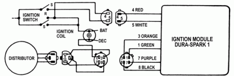
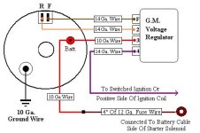
i have a three wire distributor, which I've been told after researching , tells me i have an electronic ignition i attached a copy of my ignition module wiring diagram that i am going to use. I'm going to use a toggle for the ignition and a push button for the starter. i need help understanding how to wire the voltage regular. does the fuse box get power from the voltage regulator then my ignition switch and push button start get the power from the fuse box. i also sent a diagram i was going to use for the voltage regulator its a 304
 

Attachments

  • 18C39E9.gif
    18C39E9.gif
    26.9 KB · Views: 2,461
  • gmregulator_zps68f904dd.jpg
    gmregulator_zps68f904dd.jpg
    29.8 KB · Views: 7,811

I dont know much about electronic ignitions so no help to you there, sorry. The fuse box doesnt send out any power at all.. Its just a fuse holder so the fuse blows before frying your component if to much voltage is present. You can put a fuse any where in the wire between the two components and it will serve the prepose as the fuse box. The box just holds all the fuses in one convinent area.
 
So based on what you have submitted in this schematic and what you have described, I would install your toggle switch (to kill/shut off ignition?) on the "red" wire from the battery post after the in-line fuse 69jeepcj recommended. The push button will get installed on the purple wire between a constant power source and terminal #4. You could actually use the battery post to do this as well, regardless I would put another in-line fuse on this line.


I will say that this is a guess on my part without seeing what you have specifically. I realize you already have these parts, but this project is more suited for a single wire HEI distrubution system.

Good Luck

I left out the part about the purple wire would need to signal the starter as well...... After the push button switch, you'll need to install a 12V mini relay (STDP) with the N.O. pole connected to the starter relay. Again, going off what info you have provided?????
 
Back
Top