You are using an out of date browser. It may not display this or other websites correctly.
You should upgrade or use an alternative browser.
You should upgrade or use an alternative browser.
electric fan
- Thread starter ROade
- Start date
currupt4130
VT Hokie
Adams Jeep in MD Show this weekend
hmmm taurus fans are popular, heres a link to a discussion on putting them in and their a hell of alot cheaper than flex a lite
http://www.jacksongalleries.com/alex/jeep/taurusfan/
hmmm taurus fans are popular, heres a link to a discussion on putting them in and their a hell of alot cheaper than flex a lite
http://www.jacksongalleries.com/alex/jeep/taurusfan/
Tombredone
New member
What about a donor fan for a '79 6cycl CJ-5?? Any ideas?
Bounty__Hunter
Super Moderator
Get a Ford Taurus electric fan, '90 to '95, also found in Lincoln Mark VII and Sable. Get the one that came with the 3.8L engine, it's 2-speed, pulls a ton of air, and closely matches the size of most jeep radiators.
Last edited:
Bounty__Hunter
Super Moderator
Let us know what you think.
What relays are you going to use?
What relays are you going to use?
dunlop radial mud rovers
Well,fans installed.
I used wiring as per the link someone posted .
I really dont like how they did it.
Probally gonna redo.
They have the thermostat running on high spped and manual on low.
Shouldnt it be opposite??
If noting else but to save on power draw.
???????????????????????
Well,fans installed.
I used wiring as per the link someone posted .
I really dont like how they did it.
Probally gonna redo.
They have the thermostat running on high spped and manual on low.
Shouldnt it be opposite??
If noting else but to save on power draw.
???????????????????????
Hi,
I looked at the site which was linked to in an above post. It says that the ford fan pulls up to 100 amps at start up and 33 amps continuous.
Now, I can imagine a large fan pulling 33 amps at 12 volts, that sounds reasonable. But 100 amps? That sounds a tad high to me. I know of 12 volt (electric) power steering pumps which pull a max of 80 amps at 12 volts. This is a pump which is pulling 80 amps while pushing against very high pressure when the power steering is turned to a stop. So, I just can't imagine a free spinning fan motor to pull 100... but anything is possible.
If it does pull up to 100 amps, you'd want to be using #8 AWG wire or greater and a heavy duty relay. NOTE that most solenoids are NOT made for continuous use, so if you choose to use a solenoid, be sure it is rated for continuous use. I doubt a starter solenoid is rated for such use.
If it turns out the fan pulls less than 75 amps, Bosch makes a line of nice power relays. http://www.waytekwire.com/ is one site which sells them. For example waytek part #75252 is a 75 amp with built in diodes.
Hope that helps :mrgreen:
-Nick :!:
Bounty__Hunter
Super Moderator
Great info Nick. I've also heard that standard starter relays are not good for the continuous use in a fan application. Napa carries an 80A relay for golf carts that's rated for continuous use, but they want about $31 each.
I've got a switch rated for 50A, so my low speed will be run through the switch without a relay. I'll have a Bosch 80A relay for the high speed. I read somewhere where a jeeper checked his fan and it pulled nowhere near 100A on high startup.
I just got done putting my Ford Taurus fan in my '95 YJ, I can believe how easy it was and how well it fit the YJ radiator. Upper DS hole lined up, had to drill the lower DS hole in the shroud. The PS of the shroud just required 2 L brackets to fit the factory shroud mounting points.
Thanks :mrgreen:
Snitty, to my knowledge most automotive style relays are rated for continuous use. It is more a concern when dealing with Solenoids, as some Solenoids are NOT rated for continuous use. For those who don't know, a Solenoid (and like-wise a contactor) is basically the same as a relay, except on a larger scale.
Main things that would affect the duration of time that a solenoid/relay/contactor could be used for would be how the contacts are configured (if they are large enough to support the load for an extended period of time), the type and gauge wire used for the solenoid/relay/contactor coil (small wire may heat up and either melt completely or melt the varnish coating and short circuit).
I'd imagine in a continuous use solenoid/relay/contactor they make sure the coil is made in such a way that it will not overheat and they use larger contact surfaces which will handle the load better (smaller contacts may handle the load fine for a short period of time, but could be derated by heat which would be an issue when current is flowing across them for long periods of time).
As you'd imagine these things aren't really a concern in situations such as starter motor circuits where on average the solenoid/relay are only powered for 10 seconds or less. That's why I'd recommend against using any "starting" solenoid.
If you can't find a relay large enough, try to buy a DC "contactor" as usually these are rated for continuous use, where as solenoids aren't
Oh and always use protection.... you need to use a circuit breaker or fuse to protect any circuit, especially high current circuits :mrgreen:
-Nick :!:
Bounty__Hunter
Super Moderator
Nick, how important is it to use the freewheeling diodes as in this diagram:

Hi,
First, to answer the question about the diodes: they are NOT required but are a good thing to use anyways. the site linked to above says:
This is the right idea except that it is NOT the motor which could get damaged, but the relays or wiring. However, it really isn't mandatory that Diodes are used, just a good practice. ALWAYS be sure that you have the diodes installed the correct way around (notice the direction of the triangle in schematics), as installing them backwards WILL result in a DEAD SHORT.
Also, I was looking at the schematics provided by the other websites, and didn't really like them. The thing that bothered me most was the hand-drawn schematic on the linked to site above which could allow the motor to be receiving power to BOTH the low and high inputs at the same time - - something which I would really try to avoid.
So I drew a new schematic :mrgreen: Notice in my schematic (below) that the switch used is a Double Pole Double Throw (DPDT) toggle switch, where it is like two separate switches in one (the left and right sides do NOT connect). Also Note that ALL colored wiring is HOT, where as black is Ground, and all wiring to the relay's #30/87 terminals and the motor is #10 AWG or larger, while the rest of the control wiring is #16 or #14 AWG. Also, the manual control turns the motor on HIGH, where the A/C or Temp switch (Automatic controls) turn the fan on LOW. This could be easiy reversed if your Jeep runs too hot and needs the automatic controls to run the fan on high.

Have fun :mrgreen:
-Nick :!:
First, to answer the question about the diodes: they are NOT required but are a good thing to use anyways. the site linked to above says:
"Because the fan is an electric generator when it is still spinning and off, it can store a slight charge, which has to be bled off somehow to keep the fan from damaging itself. Using the radioshack diode suggested will allow the fan to discharge itself.
This is the right idea except that it is NOT the motor which could get damaged, but the relays or wiring. However, it really isn't mandatory that Diodes are used, just a good practice. ALWAYS be sure that you have the diodes installed the correct way around (notice the direction of the triangle in schematics), as installing them backwards WILL result in a DEAD SHORT.
Also, I was looking at the schematics provided by the other websites, and didn't really like them. The thing that bothered me most was the hand-drawn schematic on the linked to site above which could allow the motor to be receiving power to BOTH the low and high inputs at the same time - - something which I would really try to avoid.
So I drew a new schematic :mrgreen: Notice in my schematic (below) that the switch used is a Double Pole Double Throw (DPDT) toggle switch, where it is like two separate switches in one (the left and right sides do NOT connect). Also Note that ALL colored wiring is HOT, where as black is Ground, and all wiring to the relay's #30/87 terminals and the motor is #10 AWG or larger, while the rest of the control wiring is #16 or #14 AWG. Also, the manual control turns the motor on HIGH, where the A/C or Temp switch (Automatic controls) turn the fan on LOW. This could be easiy reversed if your Jeep runs too hot and needs the automatic controls to run the fan on high.
Have fun :mrgreen:
-Nick :!:
Last edited by a moderator:
Me too, What are you trying to isolate?Snitty said:ok, what is the purpose for the diodes at the ground... i've often wondered that
Hi,
I meant to also add to my post up there that there should be NO need to use diodes at the motor if you use the Bosch power relay part number which I mentioned in an earlier post, as that particular relay has built in series/ parallel diodes. Ohter bosch relays do not, however, so be sure you get the correct one. :mrgreen:
-Nick :!:
Bounty__Hunter
Super Moderator
Nick, can you draw me a diagram? I'm looking to wire it up so the power to the thermostat is switched, and when hot you can select between low or high. I've got a 3-position switch where up and down will control the two speeds (If the thermostat energizes the switch) and the center pos. is all off. The switch is rated to handle the amp pull on the low speed, and I'd like to run the high speed through the relay. I've got enough relays that I can run both speeds through them if needed.
Thanks.
Thanks.
Front end possessed by devil
Hi,
First off, I have modified my schematic above as it is best to get power for the toggle switch through the ignition switch so you are assured the fan cannot be left running by accident after the Jeep is off. The first time I drew it, this was not indicated.
Bounty, a simple modification of my first schematic above gives you a circuit which does what you've asked: allows you to select the speed of the fan, with the fan being automatically switched by the thermostat. Leaving the toggle in the center position acts as an override and the fan will always remain OFF (good for water crossings). It also is in no way switched by the A/C so be sure it is always running when the A/C is on (if applicable). Also, both speeds are run through a relay, which is the safest way to do it. :mrgreen:
Here is control circuit #2 (a modification of my first schematic):
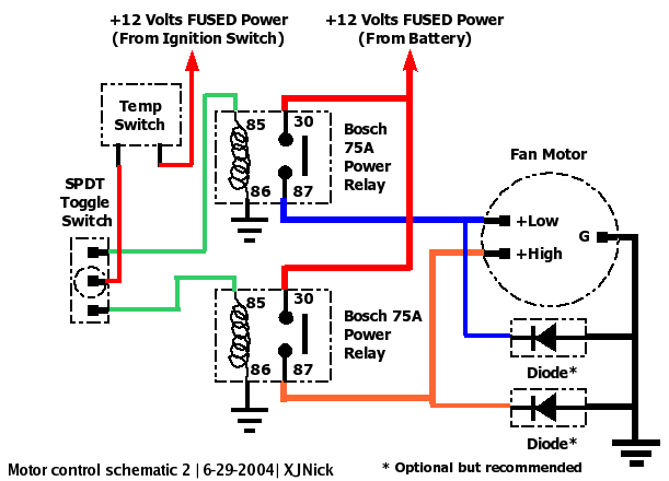
-Nick :!:
Hi,
First off, I have modified my schematic above as it is best to get power for the toggle switch through the ignition switch so you are assured the fan cannot be left running by accident after the Jeep is off. The first time I drew it, this was not indicated.
Bounty, a simple modification of my first schematic above gives you a circuit which does what you've asked: allows you to select the speed of the fan, with the fan being automatically switched by the thermostat. Leaving the toggle in the center position acts as an override and the fan will always remain OFF (good for water crossings). It also is in no way switched by the A/C so be sure it is always running when the A/C is on (if applicable). Also, both speeds are run through a relay, which is the safest way to do it. :mrgreen:
Here is control circuit #2 (a modification of my first schematic):
-Nick :!:
Similar threads
- Replies
- 6
- Views
- 7K
- Replies
- 61
- Views
- 7K