How To:
http://www.allaboutcircuits.com/vol_1/index.html
LEARNING OBJECTIVES
- How to measure current with a multimeter
- How to check a multimeter's internal fuse
- Selection of proper meter range
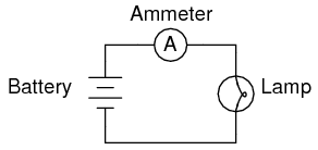
SCHEMATIC DIAGRAM
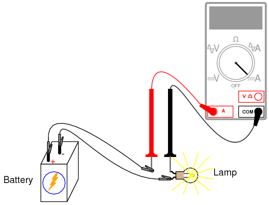
ILLUSTRATION
INSTRUCTIONS
Current is the measure of the rate of electron "flow" in a circuit. It is measured in the unit of the Ampere, simply called "Amp," (A).
The most common way to measure current in a circuit is to break the circuit open and insert an "ammeter" in
series (in-line) with the circuit so that all electrons flowing through the circuit also have to go through the meter. Because measuring current in this manner requires the meter be made part of the circuit, it is a more difficult type of measurement to make than either voltage or resistance.
Some digital meters, like the unit shown in the illustration, have a separate jack to insert the red test lead plug when measuring current. Other meters, like most inexpensive analog meters, use the same jacks for measuring voltage, resistance, and current. Consult your owner's manual on the particular model of meter you own for details on measuring current.
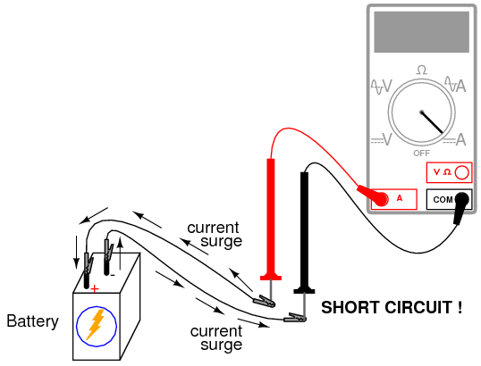
When an ammeter is placed in series with a circuit, it ideally drops no voltage as current goes through it. In other words, it acts very much like a piece of wire, with very little resistance from one test probe to the other. Consequently, an ammeter will act as a short circuit if placed in parallel (across the terminals of) a substantial source of voltage. If this is done, a surge in current will result, potentially damaging the meter:
Ammeters are generally protected from excessive current by means of a small
fuse located inside the meter housing. If the ammeter is accidently connected across a substantial voltage source, the resultant surge in current will "blow" the fuse and render the meter incapable of measuring current until the fuse is replaced.
Be very careful to avoid this scenario!
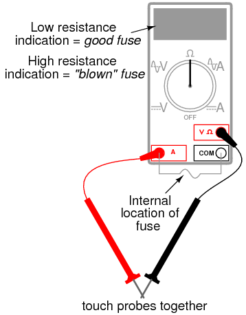
You may test the condition of a multimeter's fuse by switching it to the resistance mode and measuring continuity through the test leads (and through the fuse). On a meter where the same test lead jacks are used for both resistance and current measurement, simply leave the test lead plugs where they are and touch the two probes together. On a meter where different jacks are used, this is how you insert the test lead plugs to check the fuse:
Build the one-battery, one-lamp circuit using jumper wires to connect the battery to the lamp, and verify that the lamp lights up before connecting the meter in series with it. Then, break the circuit open at any point and connect the meter's test probes to the two points of the break to measure current. As usual, if your meter is manually-ranged, begin by selecting the highest range for current, then move the selector switch to lower range positions until the strongest indication is obtained on the meter display without over-ranging it. If the meter indication is "backwards," (left motion on analog needle, or negative reading on a digital display), then reverse the test probe connections and try again. When the ammeter indicates a normal reading (not "backwards"), electrons are entering the black test lead and exiting the red. This is how you determine direction of current using a meter.
For a 6-volt battery and a small lamp, the circuit current will be in the range of
thousandths of an amp, or
milliamps. Digital meters often show a small letter "m" in the right-hand side of the display to indicate this metric prefix.
Try breaking the circuit at some other point and inserting the meter there instead. What do you notice about the amount of current measured? Why do you think this is?
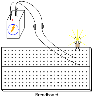
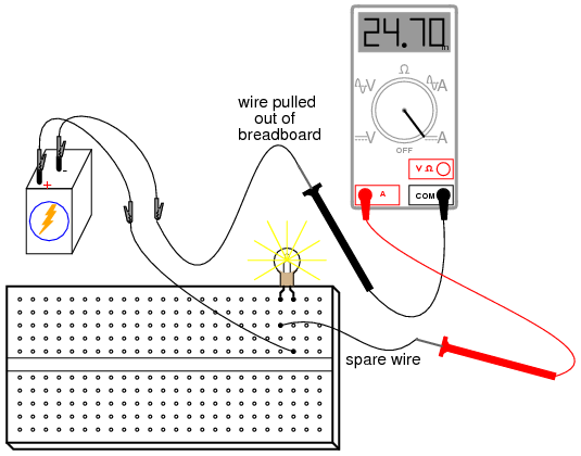
Re-construct the circuit on a breadboard like this:
Students often get confused when connecting an ammeter to a breadboard circuit. How can the meter be connected so as to intercept all the circuit's current and not create a short circuit? One easy method that guarantees success is this:
- Identify what wire or component terminal you wish to measure current through.
- Pull that wire or terminal out of the breadboard hole. Leave it hanging in mid-air.
- Insert a spare piece of wire into the hole you just pulled the other wire or terminal out of. Leave the other end of this wire hanging in mid-air.
- Connect the ammeter between the two unconnected wire ends (the two that were hanging in mid-air). You are now assured of measuring current through the wire or terminal initially identified.
Again, measure current through different wires in this circuit, following the same connection procedure outlined above. What do you notice about these current measurements? The results in the breadboard circuit should be the same as the results in the free-form (no breadboard) circuit.
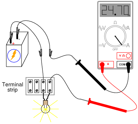
Building the same circuit on a terminal strip should also yield similar results:
The current figure of 24.70 milliamps (24.70 mA) shown in the illustrations is an arbitrary quantity, reasonable for a small incandescent lamp. If the current for your circuit is a different value, that is okay, so long as the lamp is functioning when the meter is connected. If the lamp refuses to light when the meter is connected to the circuit, and the meter registers a much greater reading, you probably have a short-circuit condition through the meter. If your lamp refuses to light when the meter is connected in the circuit, and the meter registers zero current, you've probably blown the fuse inside the meter. Check the condition of your meter's fuse as described previously in this section and replace the fuse if necessary.